Project Overview:
I would highly recommend looking at my smart environement tool kit project which builds on top of the foundations of this project. This page is effectively the initial project that the smart enviroment kit built upon and mainly covers the base of the project so how the microbits function, the messaging, how its proccessed on a computer and it also covers the things which were either removed from the tool kit project or were done differently. As such the amount of screenshots or videos of the smart lab stuff is limited on this page, please click HERE if you want to see that. With that being said I did make quite a few features which werent continued into the next project and are detailed below.
This project was to build a smart lab focusing on one room rather then a generalisable system that could be applied to multiple rooms buildings etc that the other project had us make so this is very much the barebones of that and getting to understand microbits and full stack developlement. I wont go into the API or website side of stuff for this project as it is covered extensively here. The smart lab had to be cable of tracking a users movement between zones(different areas) of the lab, it has to live update the temperature, sound level and light level, lights have to be controllable from a microbit controller, notify user of movement of chairs and it has to provide social media updates. All this was done with microbits and one computer with a microbit plugged into one of the USB ports.
The structure of the system
Here is a drawn diagram of the structure of the system :
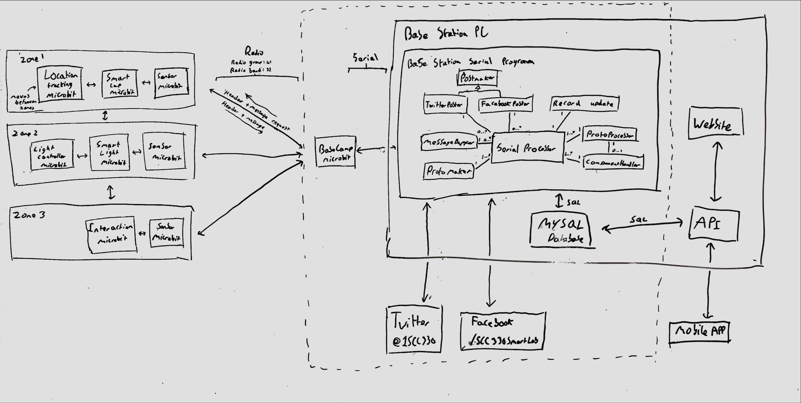
The structure of the system is similar to the other project as it has microbits performing various tasks then comunicating over radio with each other in a mesh network following atomic multicast and then once the microbit plugged into the pc (Base camp microbit) then it writes over serial the messages and the basestation then processes these messages updates a MySQL database and sends out the relevant twitter and facebook post if needed. The API then has various routes setup to get the relevant data from the database and the website then calls upon these routes to populate the websites data and it continually calls upon some of these routes every 5 seconds to update data real time. Finally you can also configure the microbits from the website so enabling and disabling any services.
Microbits
So for this project I had extensive experience working on the microbits in C++ using the codal library and I would write the code using the library in C++ which would then get turned into hex and then you flash this hex onto the microbits. The codal library itself doesnt have much documentation so it meant I spent a while reading through it and needing to have our own local editted version and the library didn’t expect people to use the microbits how we did. One example of such is our messages where 33 bytes and Codal arbitrarily limits it to 32 with no commments on why so we had to change that to 64 bytes (microbit can support radio messages up to 256 bytes) and then extensively test this to ensure nothing broke.
The microbits messaging with Protobuffers
I worked on the microbits with another person, he focused on the sensors , I did the basecamp and we both dealt with the messaging and testing. So i will only go into detial on my side of things the basecamp and the messaging.
For the messaging the the main concern was that the messages was processed over not only C++ but also Java so I couldn’t rely on using structs in C++ as its processed differently in Java. So the solution was to use Googles Protocol Buffers and specifically the embedded C++ library as the microbits had limited space and no libraries built into it. However not all proto buffers were the same length as they grow dynamically so for radio its fine as you just send a packet and your not just continually reading a buffer but for serial you are just continually reading a buffer so I had to also send a 4 byte int which would state the size of the proto buffer that was going to be processed that way the Java program knew what to read on the serial buffer. Then for the structure of our protocol buffers each had a header that would contain the relevant information that any message need like the target id, the message type etc and the protobuffer file for this message is:
1
2
3
4
5
6
7
8
9
10
11
12
13
14
15
16
17
18
19
20
21
22
23
24
25
26
27
28
29
30
31
32
33
34
35
36
37
38
39
40
41
42
syntax = "proto3";
/*
Header to be sent before all messages specifiying the message type.
*/

//Exhaustive enum of all message types.
enum MessageType{
    TEMPERATURE_RESULTS = 0;
    NOISE_RESULTS = 1;
    LIGHT_RESULTS = 2;
    TEMPERATURE_REQUEST = 3;
    NOISE_REQUEST = 4;
    LIGHT_REQUEST = 5;
    INTERACTION_DETECTED = 6;
    ZONE_CHANGE_REQUEST = 7;
    ZONE_CHANGE_ACK = 8;
    SENSOR_SEARCH = 9;
    SENSOR_ACK = 10;
    TRACKING_ZONE_REQ = 11;
    TRACKING_ZONE_CUR = 12;
    TRACKING_PING = 13;
    TRACKING_ACK = 14;
    SERVICE_CHANGE_REQ = 15;
    SERVICE_CHANGE_ACK = 16;
    SERVICE_STATUS_REQ = 17;
    SERVICE_STATUS = 18;
    SWITCH_ON = 19;
    SWITCH_OFF = 20;
    CUP_LEVEL_REQ = 21;
    CUP_LEVEL = 22;
    CUP_ANGLE_REQ = 23;
    CUP_ANGLE = 24;
}

message Header{
    MessageType message_type = 1;
    uint32 payload_size = 2;
    fixed32 message_id = 3;
    fixed64 sender_id = 4;
    optional fixed64 target_id = 5;
    uint32 zone = 6;
}
Then an attached protocol buffer would be sent which would be detailed in the payload_size and message_type detailed in the header and for example a reading of the light temperature would just be a simple message attached to the header that contains an int. However, for the enabling or disabling a service of a microbit then it contain a little bit more information and the code for that is below:
1
2
3
4
5
6
7
8
9
10
11
12
13
14
15
16
17
18
19
20
21
22
23
24
25
26
27
28
29
30
31
syntax = "proto3";

//Exhaustive enum of all controllable services.
enum SensorServices {
    None = 0;
    Interaction = 0x1;
    AmbientLight = 0x2;
    Noise = 0x4;
    Temperature = 0x8;
    Tracking = 0x10;
    Ping = 0x20;
    Lighting = 0x40;
    Cup = 0x80;
    TiltSwitch = 0x100;
}

/*
Switches a single given service on or off.
*/
message ServiceChangeRequest {
    SensorServices service_id = 1;
    bool enabled = 2;
}

/*
Message body for returning the currently enabled services.
*/
message ServiceStatusMessage {
    //A bitmap of enabled services.
    fixed32 enabled_services = 1;
}
A few final important things to note is when messaging over radio on a micorbit you must specifiy the frequancy band, group and the transmission power in order to ensure as little noise occurs even though noise will still occur. In addition the microbits also generate a random message ID to ensure no duplicate messages are processed.
The Base camp microbit
The sensors would fill out all these details of the header + message and attach the size of the header to the front and then send it as just one whole packet over radio. The Basecamp microbit was just setup event driven so each time a microbit radio message was sent then it would call a function that would display on the LED the current number of messages processed. Then it would send over serial using the codal’s function. Whenever a event happens it is processed in a seperate thread
However the Base camp provided two way communication for the enabling and disabling, so the Base station would also write to the Base camp. To deal with this after 4 bytes have been recieved from serial it calls a function. This function deserializes the data into a buffer and sets the sender id to be basecamps id and then it finds the playload size if their is one it reads the bytes from serial to get the message. Then it just adds the header size infront of the header and message and sends the size + header + message in one radio packet broadcasting to all microbits. Finally it just resets the event to state that it can now process another message as you don’t want multiple threads to be reading the serial buffer at once.
Base station
The base stations works by using a scheduler to schedule requests (request measurements from sensors etc) to be written to serial buffer, social media updates (tweets and facebook post) and check for components being enabled or disabled. This is done through the wisp scheduler and it is pretty basic which is why for the second project I switched to use the observer pattern and have listeners subscribe to events they care about. This scheduler creates a new thread whenever a scheduled event is to happen.
The main loop of the program is effectively just a while loop that continually checks for 4 bytes to be in the serial buffer and then once 4 bytes are it checks the number the 4 bytes converts to is within a normal range. Provided its not junk/corrupted then it will wait till there is enough bytes to read the header and using google’s protocol buffers the bytes are easily turned into a header. Then it gets the headers payload size and passes along the header and payload bytes. The payload is then converted to a message based off the header’s message type, at which point it will check against a cyclic message buffer to see if the message id has been proccessed yet. If it has not then the message will be handled correctly by storing the information in the MySQL database.
Social media bots
Twitter bot
The twitter account is https://twitter.com/1Scc330
For this project I made and tested extensively a twitter bot in Java which as detailed above is scheduled to tweet out information at set times. The account has just under 2000 tweets and nowadays it would impossible to do so due to the recent changes in the twitter API where tweeting from a program costs quite a bit, however when I was making it all these tweets were free. The bot worked by the base station scheduling calling functions every x minutes. The function it calls uses javas JDBC driver to connect to the MySQL DB and then it grabs the last temperature/noise/light recording and adds then posts the information using Twitter4J. Light, noise and temperature posts happen every 5 minuetes while the program is running. In addition every hour it tweets out the amount of times the chair had been interacted with. Finally every hour it would also tweet the percentages of what zone a microbit has been in so i.e what side of a room a person has been in for the last hour.
Example Light level tweet:
The last light recording was: 0 out of 255 intensity and was recorded at: 2022-12-07 17:14:19.0 UTC
— SCC330 Group 1 (@1Scc330) December 7, 2022
Example Noise level tweet:
The last noise recording was: 205 out of 255 intensity and was recorded at: 2022-12-02 14:41:28.0 UTC
— SCC330 Group 1 (@1Scc330) December 2, 2022
Example Temperature tweet:
The last temperature recording was: 28 degrees and was recorded at: 2022-11-29 17:19:13.0 UTC
— SCC330 Group 1 (@1Scc330) November 29, 2022
An example of a chair interaction tweet:
In the last hour (2022-12-08 13:00:01.0) the chair has been interacted 3 times
— SCC330 Group 1 (@1Scc330) December 8, 2022
An example of a zone tweet:
In the last hour (2022-12-07 20:00:01.0) Microbit 1 was in zone 1 50.847458% , zone 2 31.355932% and zone 3 17.79661%
— SCC330 Group 1 (@1Scc330) December 7, 2022
Facebook bot
The Facebook account is https://facebook.com/SCC330SmartLab
The Facebook bot is the exact same as the twitter bot but posts to Facebook instead and uses restFB
Example Light level post:
Example Noise level post:
Example Temperature post:
Example chair interaction post:
Example users zone post:
Closing Thoughts:
This project was first experience of working with so many different technologies and langauges together and gave me a great initial look into industry software engineering. In addition every learnt here was futher built on in the Smart Environment Toolkit.
Comments powered by Disqus.